
Uneven Drying Causes and Airflow Diagnosis
Uneven drying diagnosis uses measured symptoms and repeatable evidence to distinguish airflow, loading, sensor and material causes.
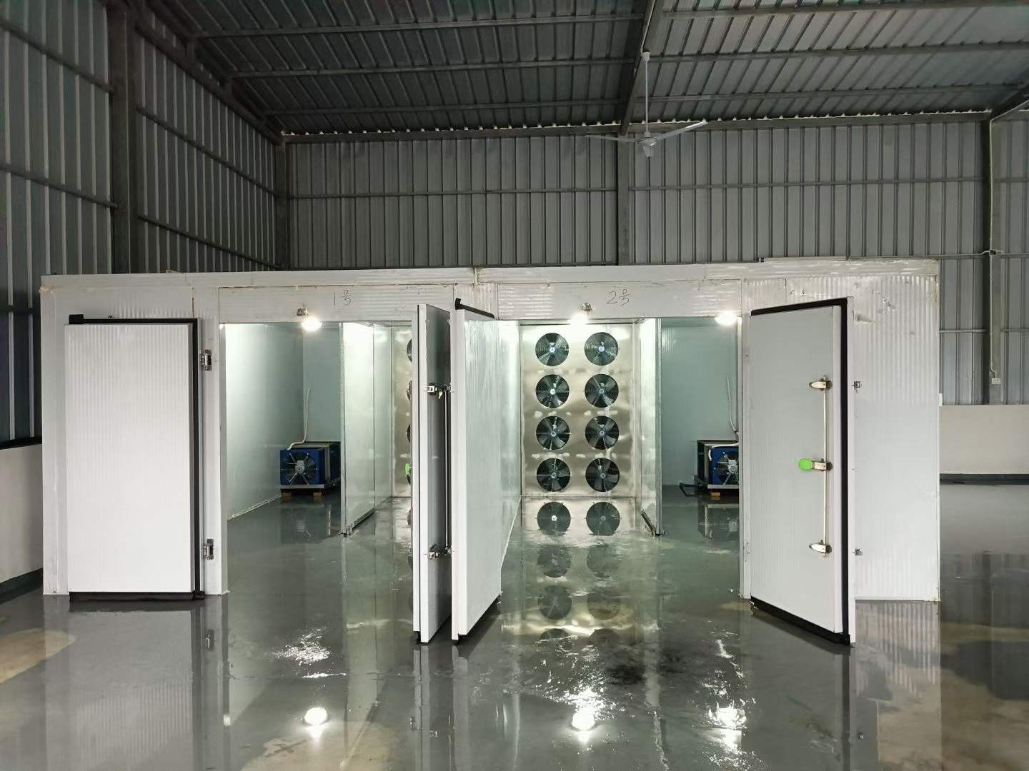
Diagnose uneven drying causes with measured evidence
Diagnosis begins with a repeatable symptom pattern, not a new setpoint. Map wet and dry locations by tray, trolley and room position, then compare material preparation, temperature, humidity and airflow evidence. Use sensor checks and one controlled correction at a time so the cause can be separated from the result.
Describe the load and the air path together
Material preparation
Record cut size, surface condition, bulk density, moisture basis and lot variation. A physical difference can look like an airflow defect.
Tray and trolley loading
Record layer condition, tray spacing, trolley alignment, wall clearances and return-air access. Avoid changing the loading basis during the comparison.
Supply and return
Mark openings, fan direction, obstructions, return zones and possible short circuits on a room plan.
Room envelope
Check doors, joints, penetrations and condensation signs. Leakage can change local conditions and distort a sensor-based conclusion.
Measurement plan
Use consistent locations, instruments and timestamps. A single room reading cannot establish uniformity across the load.
Use symptoms to choose the next check
| Pattern | Possible cause | Measurement | Corrective direction |
|---|---|---|---|
| Front differs from rear | Supply bias, trolley spacing or short circuit | Map result by position; inspect supply and return path | Review arrangement and air distribution before changing settings |
| One corner remains wet | Dead zone, obstruction or local leakage | Compare local condition with central reference and inspect envelope | Correct the physical path or leakage condition |
| Lower layers stay wet | Dense loading, blocked tray path or material variation | Record layer condition and compare airflow exposure | Review loading resistance and tray arrangement |
| Controller reaches target early | Sensor in direct air or non-representative position | Compare sensor with multiple reference points and trend timing | Review purpose and placement of the control measurement |
| Pattern changes each batch | Material or loading variability | Record lot, fresh mass, dimensions and layout | Stabilize the process brief before equipment changes |
Measure the route, not only the room average
Begin with a marked room plan showing supply, return, doors, trolleys, trays, drains and sensors. During a comparable operating stage, record the instrument location, time and material position for each observation. Where appropriate, a qualified engineer may use airflow or pressure instruments to compare planned paths, but the method, instrument and acceptance basis must be defined for the project. Do not infer a universal velocity or pressure target from a single installation.
- Preserve the current loading and control basis.
- Map the symptom by tray, trolley, layer and material lot.
- Inspect visible obstructions, bypass routes, seals and returns.
- Compare defined measurement points with a consistent method.
- Change one physical or process variable and repeat the comparison.
Consider architecture and envelope together
Open-loop and closed-loop arrangements can respond differently to ambient humidity, exhaust paths and room leakage. The choice does not remove the need for a balanced loading plan and a representative measurement strategy. A drying-room design review should connect room geometry with the tray and trolley loading plan. Compare the results with the broader airflow design rather than treating one fan setting as the whole diagnosis.
Questions buyers and operators ask
Is uneven drying always an airflow problem?
No. Material size, moisture, loading resistance, room leakage and sensor position may contribute.
Should I increase airflow immediately?
First document the baseline and inspect the path. An unmeasured change may move the symptom or create another imbalance.
What is a dead zone?
It is a region where the intended process-air movement or exchange is insufficient for the evaluated load; its cause must be checked physically.
Can one sensor prove uniformity?
No. Multiple defined observations may be needed depending on room geometry and process stage.
What information belongs in an RFQ?
Provide material form, moisture basis, batch size, tray and trolley arrangement, room drawing and any mapped symptoms.
Continue the technical review
Review uneven drying with project evidence
Send a marked loading plan, material description and available measurements to sales@hpdryer.com.
Confirm that the pattern actually changed
After a corrective direction is selected, repeat the same map using comparable material preparation, loading and process stage. Keep measurement locations and instrument method consistent. Compare wet and dry positions, not just the average result. If one area improves while another worsens, the evidence may indicate a distribution trade-off or an unrecorded loading difference. Document the remaining uncertainty and decide whether a room, fan, sensor or material review is required.
Uniformity is a process property observed under a stated basis. It is not established by a single photograph, one room reading or an isolated successful batch. A repeatable check should be part of the operating or commissioning record when uniformity matters to the buyer.