
Industrial Dryer Temperature and Humidity Sensor Placement
Temperature and humidity sensors influence both diagnosis and control, so their position must represent the process variable being evaluated. Supply air, return air, room air and material-adjacent measurements answer different questions. Placement should avoid direct jets, walls, doors and condensate zones, then be checked against a reference method during commissioning. Final locations depend on the room, material and control sequence.
Diagnose the process before changing the design
A sensor reports conditions at its own sensing element, not an abstract room average. A probe near a supply outlet may react quickly but may not represent the air reaching most of the load. A probe beside a cold wall or door can be biased by surface temperature. A humidity sensor in a condensate-prone area may drift or require protection defined by its specification.
Before selecting a location, define what the signal is used for: equipment protection, process control, alarm, commissioning comparison or troubleshooting. A control sensor and an audit sensor do not always need the same position. The project brief should record the location, height, airflow exposure, protection and intended use.
Record the variables that shape the observation
Supply air point
Useful for checking the air condition delivered from the conditioning section. Direct jet exposure can make the reading non-representative of the mixed supply path.
Return air point
Useful for observing the air condition leaving the load. The position should account for mixing and avoid a local shortcut or blocked return.
Room reference point
Useful for comparing room conditions away from direct supply, walls, doors and condensate. It may support diagnosis but should not automatically replace a control point.
Material-adjacent point
Useful when the process needs a local observation near the load. Protect the probe from contact, impact and direct wetting.
Reference instrument
A portable or calibrated reference can help identify abnormal readings during commissioning. Comparison must follow the instrument specifications and method.
Use a defined check rather than a single assumption
| Observation or input | Purpose | Risk if incomplete | Review direction |
|---|---|---|---|
| Supply duct or outlet | Delivered air condition | Direct jet or poor mixing | Compare with a downstream reference point |
| Return-air plenum | Air after passing the load | Short circuit or local obstruction | Inspect path and compare several return locations |
| Near wall or door | Envelope influence | Surface temperature and leakage | Move inward and compare under stable conditions |
| Near wet material | Local process condition | Condensation, splash or contact | Use suitable protection and compare with a dry reference |
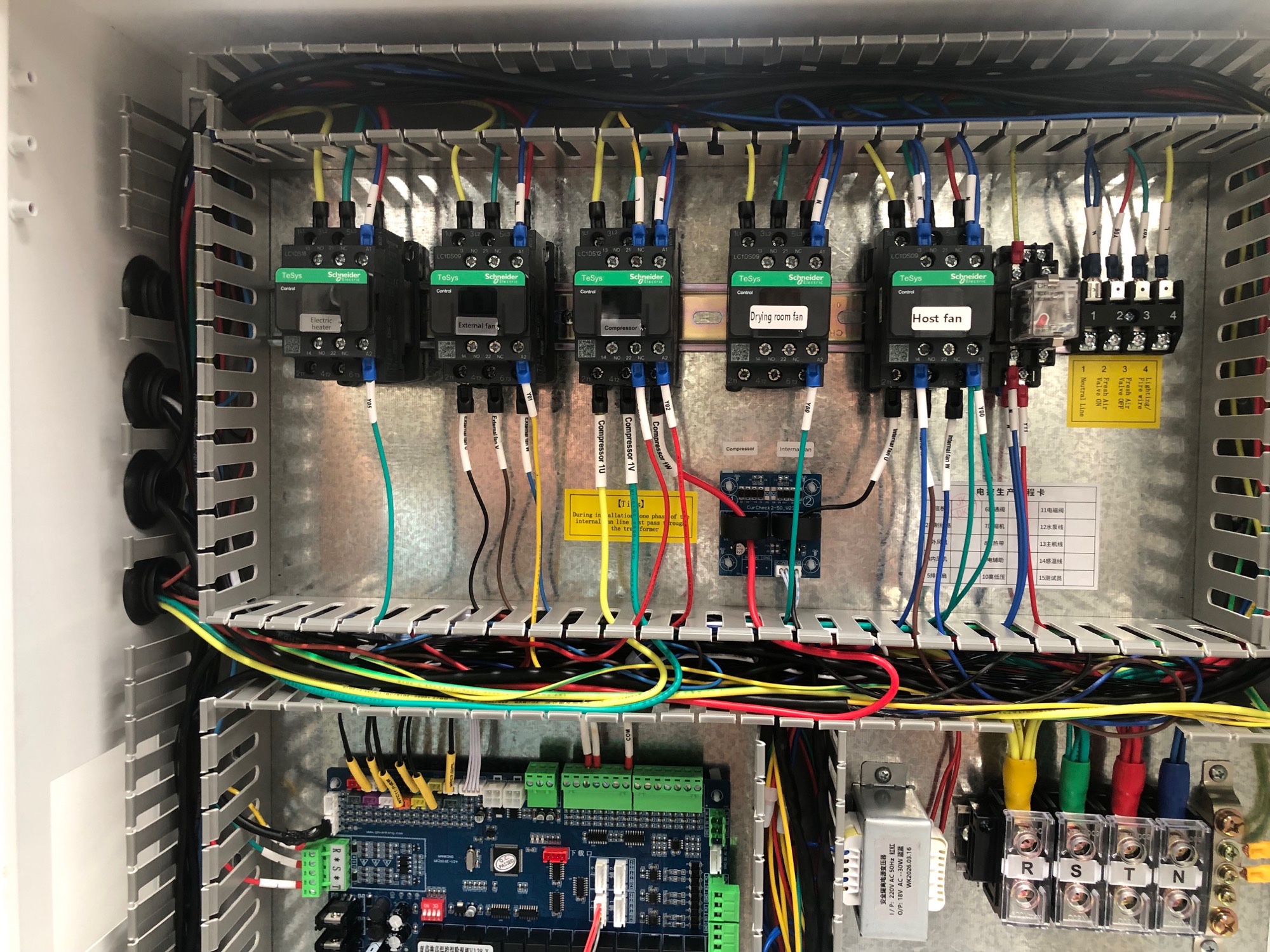
| Control cabinet input | Signal used by PLC | Wrong channel, scaling or wiring issue | Check tag, units, trend and commissioning records |
Separate evidence from interpretation
Sensor placement review starts with a drawing or marked-up room plan. Mark supply, return, door, wall, drain, trolley and material zones, then assign each sensor a purpose. Check whether the sensing element is exposed to a direct jet, a dead zone, a leakage path or a condensing surface. Record the mounting orientation, protection and cable route where these affect reliability.
During commissioning, compare the installed signal with a suitable reference method under stable conditions. Check the displayed unit, scaling, timestamp and trend direction. A plausible value can still be wrong if the channel is mislabeled or the sensor is in an unrepresentative position. The acceptance basis should be defined by the sensor specification and project requirements, not by an invented universal accuracy or calibration interval.
Define the evidence before a decision
For industrial dryer temperature and humidity sensor placement, collect the material description, preparation method, initial and target moisture basis, batch or operating schedule, loading arrangement and available room information. Record the instrument locations, measurement method and any known site constraints. Separate measured observations from estimates and identify missing data. This makes the technical discussion easier to audit and prevents a trial or symptom from being treated as a universal design value. The final recommendation depends on the confirmed project inputs, applicable safety procedures and a project-specific engineering review. Keep the original records available so later conclusions can be traced to the observed conditions.
Sensor commissioning checklist
- Confirm tag name, measurement unit and PLC channel.
- Record physical position on the room or equipment drawing.
- Check direct airflow, wall proximity, door influence and condensate exposure.
- Compare the reading with a suitable reference instrument or method.
- Trend the signal through relevant operating stages and record anomalies.
- Document any limitation and the action owner before release to operation.
Continue the technical review
Questions buyers and operators often ask
Should the control sensor be placed at the supply outlet?
Not automatically. Direct outlet air may respond quickly but can be unrepresentative. The control position should follow the process and airflow review.
Can a room sensor measure material moisture?
No. Room temperature and humidity are process-air observations, not a direct measurement of material moisture.
Is a fixed calibration interval required?
The interval should follow the sensor specification, site quality procedure and project requirements. No universal interval should be assumed.
Why do two sensors disagree?
They may be measuring different air paths, have different response characteristics, or have a wiring, scaling or condition issue. Location and instrument checks are needed.
Discuss the process with HPDRYER
Share the material condition, moisture basis, capacity, room, climate and control information available for an engineering review.