
Industrial Drying Room Insulation and Airtightness
Quick Answer
Insulation limits unwanted heat transfer, while airtightness controls unintended air and moisture movement through the drying-room envelope. Both must be reviewed as continuous systems across walls, ceiling, floor interfaces, doors, panel joints and service penetrations. The required materials and details depend on operating temperature, ambient conditions, room size, pressure behavior and local regulations; they should not be selected from one universal panel-thickness rule.
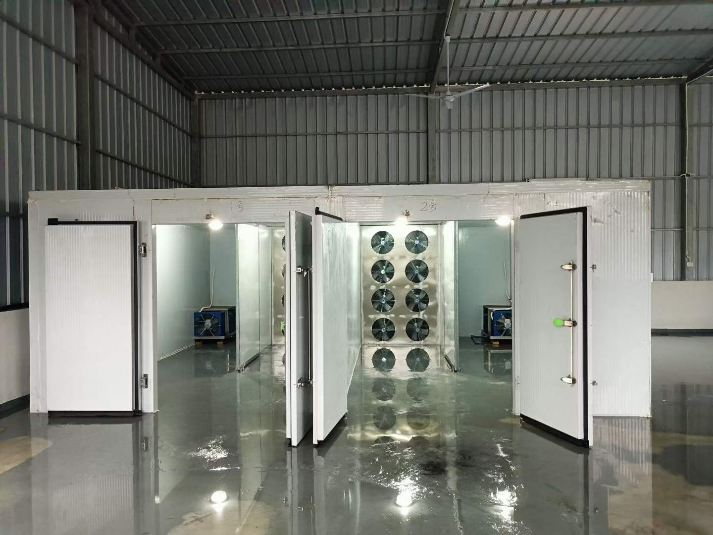
Thermal control and air control are related but different.
The drying room separates a controlled process-air volume from the surrounding factory or outdoor environment. Insulation reduces heat transfer through the enclosure. The air-control layer limits leakage driven by fan pressure, temperature difference, wind and door operation. A vapor-control layer may also be required to manage diffusion and condensation within the assembly. One material can perform more than one function, but the design must identify which layer performs each function and how continuity is maintained.
Thermal Boundary
Walls, ceiling, floor and doors should form a continuous thermal boundary around the process space. Junctions and framing require review for thermal bridges.
Air Boundary
Panel joints, door seals, ducts, drains, cables and pipe penetrations should connect to a defined air-control layer without open leakage paths.
Moisture Control
Vapor pressure direction can change with operating and ambient conditions. Vapor-retarder location and permeability therefore require project-specific analysis.
Serviceability
Seals, doors and accessible joints should be inspectable and repairable because repeated loading and cleaning can change their condition.
Most leakage risk occurs where assemblies meet.
| Location | Engineering review | Verification question |
|---|---|---|
| Wall and ceiling panels | Joint profile, seal continuity, fasteners and movement allowance. | Are all seams connected to the intended air and vapor control layers? |
| Floor perimeter | Panel-to-floor transition, drainage, cleaning exposure and possible thermal bridge. | Can water or process air bypass the enclosure at the base detail? |
| Doors | Gasket compression, frame alignment, threshold, hinges and frequent opening. | Does the seal remain continuous when the door is latched? |
| Duct and service penetrations | Flexible seals around ducts, cables, sensors, drains and refrigerant lines. | Can the detail tolerate vibration and maintenance without opening a leak path? |
| Panel damage or modification | Repair method and restoration of all control layers. | Has the thermal, air and moisture boundary been reinstated? |
Open-loop and closed-loop rooms place different demands on the envelope.
An open-loop system intentionally admits and exhausts air. The room still requires controlled leakage so that intake and exhaust behavior is defined rather than dominated by gaps. Outdoor humidity, wind and unintended openings can change room pressure and moisture removal.
A closed-loop system recirculates process air and removes moisture through a controlled path. Unplanned leakage can introduce ambient moisture or lose conditioned air, so room tightness is part of the moisture balance. Neither architecture eliminates the need to review doors, drains and service penetrations.
Use the high-humidity climate guide and open-loop versus closed-loop comparison to document the boundary conditions.
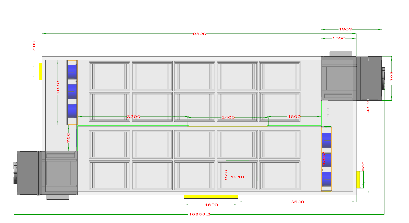
Define conditions before selecting an enclosure assembly.
- Process conditions: planned air temperature and humidity stages, operating duration and shutdown condition.
- Ambient conditions: indoor or outdoor installation, seasonal temperature and humidity, rain exposure and solar load where relevant.
- Room geometry: internal dimensions, floor construction, doors, loading openings, ducts and utility penetrations.
- Pressure behavior: fan arrangement, intended intake and exhaust, return-air path and acceptable leakage-control method.
- Hygiene and cleaning: wash-down or dry-cleaning method, drainage, chemical exposure and repair access.
- Compliance basis: locally applicable building, fire, food-contact and occupational requirements supplied by the project team.
Panel thickness, insulation type, facing material, fire classification and vapor-retarder location must be chosen against these inputs and local requirements. This page does not prescribe a universal construction.
Review continuity before the room is closed in.
Map the Boundary
Mark the continuous thermal, air and moisture-control layers on sections and details.
Detail Transitions
Resolve walls, roof, floor, doors, ducts, drains, cables and pipe penetrations.
Inspect Installation
Check clean substrates, seal placement, panel damage, gasket contact and closure.
Record and Maintain
Document accepted details and define periodic inspection after operation begins.
Continuity and project conditions govern the detail.
The NIBS Building Enclosure Commissioning guideline emphasizes inspection of vapor-control terminations, joints, seams and penetrations. The Whole Building Design Guide likewise explains that air and vapor-control layers depend on continuous, sealed joints and penetrations. These building-envelope principles inform the review method, but final drying-room construction still requires project-specific engineering and applicable local codes.
Insulation and airtightness questions
What panel thickness should every drying room use?
There is no universal value. Temperature difference, room size, ambient exposure, structure, condensation risk and local requirements must be evaluated.
Is insulation alone enough to make a room airtight?
No. Airtightness depends on continuous joints, seals, doors and penetration details, not only the insulation core.
Does an open-loop room need good sealing?
Yes. Intake and exhaust should be deliberate; uncontrolled leakage can alter pressure, airflow and moisture discharge.
How should leakage be checked?
The project team should define visual inspection and any pressure or leakage test appropriate to the room and local requirements.
Coordinate the room boundary with airflow and installation.
Review the drying room as part of the complete system.
Share the process conditions, room dimensions, site climate, openings, cleaning method and air-system architecture for an engineering review.