
Industrial Dryer Installation Requirements
Industrial dryer installation planning connects equipment dimensions with the drying room, material workflow, electrical supply, drainage, ventilation, weather protection and service access. Requirements should be confirmed for the actual project site before delivery or construction begins.
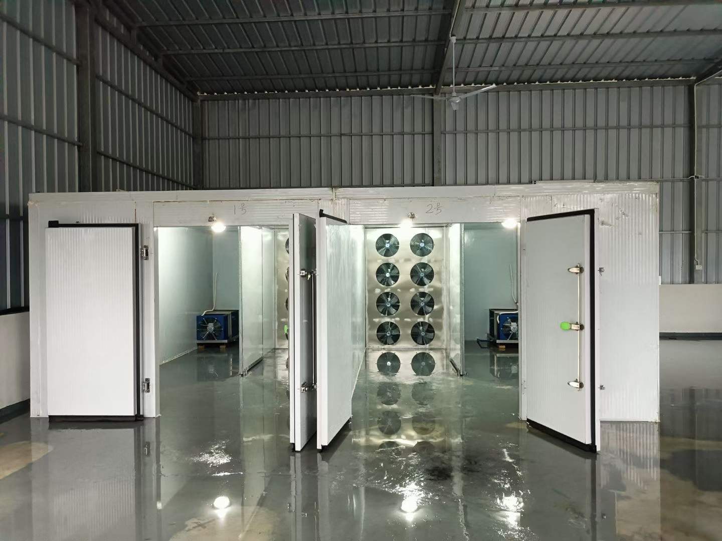
Document the installation boundary before confirming layout.
A useful site survey records available floor area, ceiling height, access routes, structural constraints, utility locations, indoor or outdoor exposure and the planned material flow. Photographs and dimensioned sketches can clarify obstacles, but the customer and supplier should agree which civil, electrical, drainage, ventilation and lifting work belongs to each party.
Equipment Footprint
Confirm operating footprint, service clearances, heat-exchanger access and space for ducts, valves, panels and drains.
Drying Room Footprint
Include usable loading area, supply and return-air zones, doors, insulation thickness and trolley movement.
Material Workflow
Map preparation, staging, loading, unloading and finished-product movement without blocking maintenance access.
Delivery Route
Check gates, roads, elevators, corridors, door openings, lifting points and temporary storage before equipment arrives.
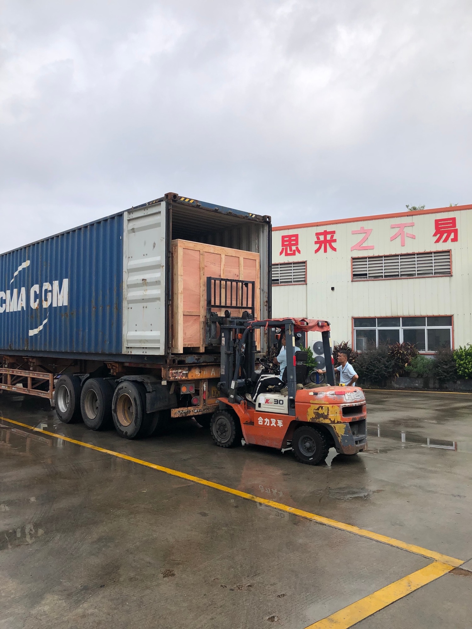
Exchange site utility information early.
| Installation item | Information to confirm |
|---|---|
| Electrical supply | Voltage, frequency, phases, available capacity, cable route, protection concept and local connection responsibility. |
| Control wiring | Panel location, sensor routes, communication requirements, emergency stops and operator access. |
| Condensate drainage | Drain location, elevation, slope, trap requirements, discharge route and cleaning access. |
| General drainage | Whether floor cleaning, product drip or room washdown creates separate drainage needs. |
| Water or other utilities | Any project-specific cleaning, process or auxiliary requirement identified during engineering. |
Electrical, building and drainage work must follow the requirements applicable to the project location. This page does not claim compliance with a particular national standard.
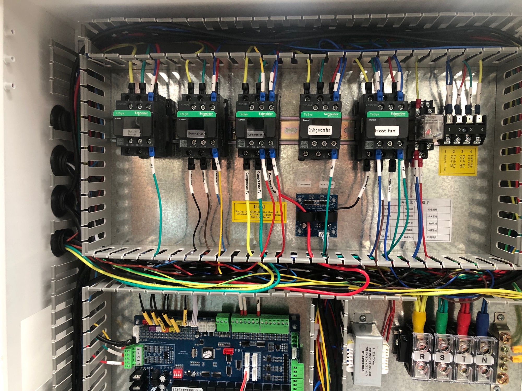
Plan for loading, inspection and future service.
Installation drawings should show more than the machine outline. Operators need safe access to load and unload the room. Maintenance personnel need practical space to inspect filters, fans, heat exchangers, refrigeration components, drains, sensors and control cabinets. Doors and removable panels should not be blocked by walls, stored materials or fixed services.
- Loading access: trolley turning radius, ramps, thresholds and staging space.
- Maintenance access: service sides, overhead clearance and component removal paths.
- Cleaning access: floor edges, drain pans, ducts, filters and product-contact supports.
- Emergency access: exits, isolation points and local project safety review.
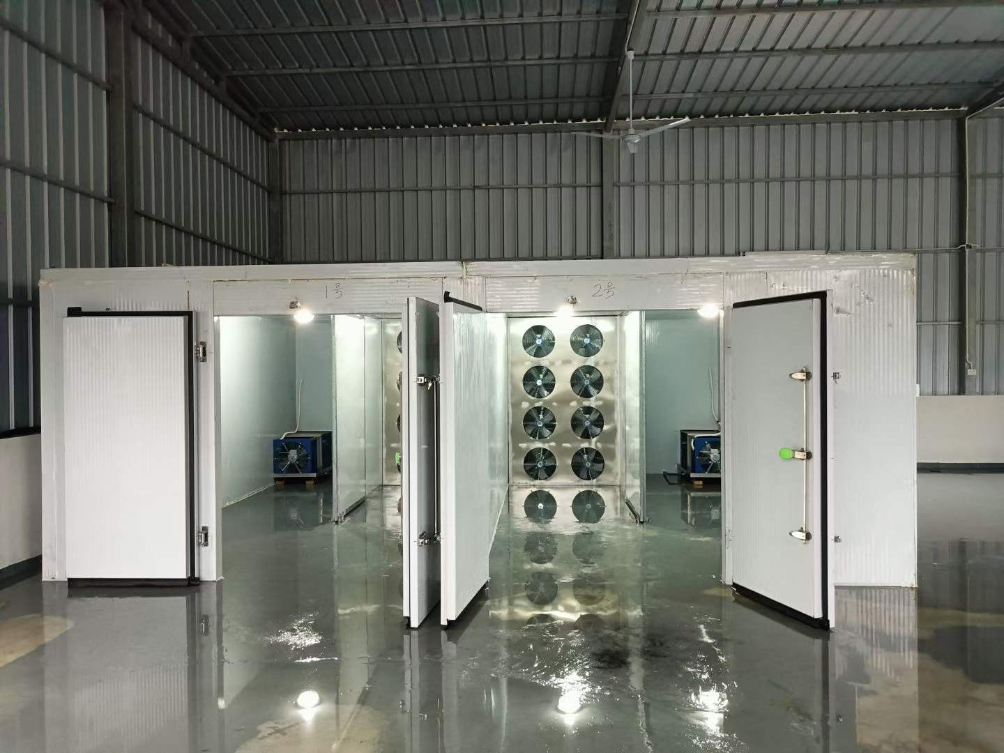
Open-loop and closed-loop installations need different site provisions.
| Review point | Open-loop installation | Closed-loop installation |
|---|---|---|
| Air connection | Fresh-air intake and exhaust openings, ducts and weather protection require coordination. | A defined recirculated process-air circuit and room-envelope condition require coordination. |
| Location effects | Intake air quality, recirculation of exhaust, wind and ambient climate can influence operation. | Door openings, leakage, insulation and vapor behavior can influence control and heat loss. |
| Moisture discharge | Moist exhaust must be routed to an acceptable discharge location. | Condensate drainage and any planned air exchange must be routed correctly. |
| Room pressure | Intake and exhaust balance should be reviewed with doors and adjacent spaces. | Leakage and unintended pressure paths should be limited by the room design. |
Support the equipment and protect the installation environment.
The site should confirm floor loading, levelness, drainage slope and any foundation or anchoring requirement with the relevant local professionals. Outdoor or semi-outdoor equipment may require protection from rain, direct contamination, flooding, corrosive exposure or restricted ventilation. Weather covers must not obstruct airflow or maintenance access. The final arrangement should use approved project drawings rather than generic assumptions.
Confirm readiness before startup.
Mechanical Check
Verify placement, clearances, ducts, room, doors, loading hardware, drains and fasteners against approved drawings.
Electrical Check
Confirm supply information, protection, wiring, phase condition, grounding and control connections by qualified personnel.
Air and Sensor Check
Inspect fan direction, dampers, filters, air paths, sensor positions and unobstructed loading zones.
Process Readiness
Agree the trial material, loading plan, operating responsibility, observation records and acceptance approach.
Clarify customer and supplier responsibilities.
Customer Site Data
Dimensions, utility information, climate, civil conditions, access limitations and local requirements.
Supplier Technical Data
Equipment dimensions, connection points, service clearances, loads and approved installation drawings.
Scope Boundary
Responsibility for room work, power, drainage, ducts, foundations, lifting, commissioning and operator preparation.
Change Control
How site changes, revised dimensions or unavailable utilities will be communicated and reviewed before installation.
Connect installation with the selected process.
Review installation requirements before finalizing the system.
Share the site dimensions, utility information, access conditions, planned room and material workflow with HPDRYER.