
Drying Tray and Trolley Loading Design
Quick Answer
Tray and trolley design determines how material is presented to process air. Product dimensions, layer depth, loading density, tray open area, rack spacing and trolley position all affect resistance and air distribution. Fixed spacing or layer-thickness rules cannot be applied to every material. The loading arrangement should be developed with material testing, airflow review, handling needs and the required batch capacity.
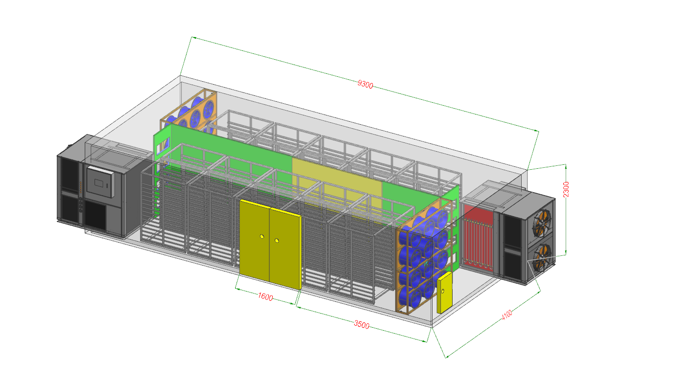
The material support becomes part of the air path.
A drying room can have adequate fan capacity yet produce uneven exposure if air bypasses the trays, meets excessive resistance through a deep load, or returns before crossing the product. Tray perforations, mesh, solid areas, rack frames and trolley geometry create pressure loss. The product itself adds resistance that may change during shrinkage. Design therefore starts with the loaded condition, not an empty-room air velocity.
Material Form
Record whole, sliced, chipped, shredded, granular or irregular form, including dimensional variation and breakage sensitivity.
Layer and Density
Define the proposed layer depth, mass per tray and bulk density as test inputs rather than universal values.
Tray Geometry
Review usable area, open area, edge profile, material retention and how the tray sits in the rack.
Trolley Position
Document rows, gaps, alignment, wheel stops, loading direction and clearance from supply and return zones.
Control bypass paths and local dead zones.
| Observed condition | Possible loading cause | Engineering check |
|---|---|---|
| Fast drying near one wall | Large side clearance creates a low-resistance bypass path. | Review baffles, trolley alignment and wall clearance without blocking required service access. |
| Wet trays inside a rack | Layer resistance, closed tray area or insufficient space between loaded trays. | Measure the loaded pressure and compare exposure at representative positions. |
| Uneven top-to-bottom result | Supply distribution, rack geometry or return position favors part of the trolley. | Map the full supply-to-return path and inspect obstructions. |
| Result changes between batches | Inconsistent product preparation, tray mass or trolley location. | Standardize the loading record and compare equivalent positions. |
| Material moves or deforms | Local air force is too concentrated for the material form. | Review support surface and distribution rather than reducing all system airflow blindly. |
Protect supply and return zones.
Trolleys should be positioned so process air cannot take an easier route around the load than through the intended exposure area. Wall and ceiling gaps, open spaces between trolley rows and an unprotected return can create bypass. At the same time, clearances may be needed for doors, drainage, cleaning, operators and safe handling.
Wheel guides or marked loading positions can improve repeatability. Removable baffles may be considered where the room must accept different loading formats, but their effect should be checked in the loaded condition. Review the relationship with drying room design before fixing room dimensions.
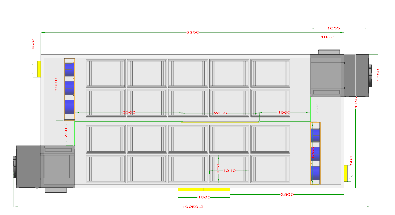
Loading hardware must work through the complete batch cycle.
The engineering review should include preparation, filling, transport, room loading, unloading and cleaning. Tray weight and trolley stability affect operator handling. Trays should retain the specified material form while permitting the intended airflow. Where the product is handled under food or hygiene requirements, the owner must define applicable contact-material, cleaning and contamination-control requirements; this page does not prescribe a material grade or certification.
- Preparation: cutting, draining, pre-treatment and time before loading.
- Loading: target mass per tray, distribution method and acceptable variation.
- Movement: trolley path, doorway, floor condition, turning space and restraints.
- Cleaning: access to tray surfaces, rack joints, wheels and room areas behind the load.
- Traceability: batch, trolley and representative tray positions used for observations.
Define the load before final airflow selection.
| Input | Information to provide |
|---|---|
| Material | Product form, dimensions, fragility, stickiness, shrinkage and preparation. |
| Batch | Fresh mass, number of trays and trolleys, expected loading variation and daily schedule. |
| Moisture | Initial and target moisture on a consistent basis plus expected water removed per batch. |
| Support | Tray dimensions, perforation or mesh, rack spacing, trolley frame and available samples or drawings. |
| Room | Internal dimensions, doors, supply and return positions, drainage and handling clearances. |
| Verification | Material test plan, tray-position sampling and observations needed to confirm repeatability. |
Coordinate these inputs with the capacity calculation and the relevant page in Industrial Drying Applications.
Check the arrangement in the loaded state.
Prepare Consistently
Record material dimensions, surface condition and representative mass per tray.
Map Resistance
Review tray open area, layer depth, rack frames and the change as material shrinks.
Control Position
Define trolley rows, wall gaps, supply clearance, return clearance and repeatable stops.
Verify the Batch
Compare representative locations and revise loading or airflow only from recorded observations.
Tray and trolley design questions
What tray spacing should be used?
It depends on material dimensions, layer resistance, airflow direction, rack geometry and testing. No spacing fits all products.
Can more material simply be added to each tray?
A deeper or denser load can increase resistance and change exposure. Capacity must be assessed with drying time and uniformity.
Why do edge trays dry differently?
Side bypass, wall clearance, supply distribution or return position may create a lower-resistance air path.
Should airflow be checked in an empty room?
Empty-room checks are useful, but final assessment must include loaded trolleys because the product and supports change resistance.
Loaded geometry can create measurable drying differences.
A USDA Agricultural Research Service study found substantial spatial variation across trays in a cabinet dryer and identified tray configuration and fan placement as airflow-design questions. The study does not define a universal industrial arrangement; it supports measuring representative loaded positions instead of assuming that an empty chamber or one tray describes the whole batch.
Connect loading geometry to room and system design.
Review the actual material and loading arrangement.
Share product form, tray and trolley details, fresh batch mass, room layout and any available material-test observations.